A logic gate is an electronic circuit that operates on one or more input signals to produce an output signal.
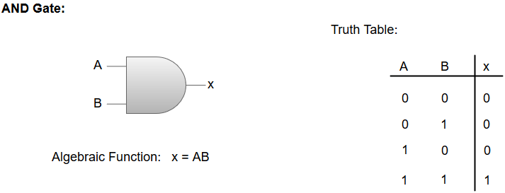
1. AND GATE: AND gate is an electronic circuit that produces high (1) output when all the inputs are high. Otherwise, the output will be low (0). It can have two or more outputs and produces a single output.
Graphical symbol,
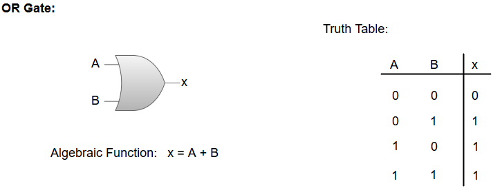
2. OR GATE: OR gate is an electronic circuit that produces high (1) output when one of the inputs is high (1). If all inputs are low then the output will be also, low (0). It has two or more inputs and Produced a single output. Graphical symbol
3. NOT gate: NOT gate is an electronic circuit whose output is the complement of the input. 9t is also called an inverter. If we produce high input (1) to this gate, it will produce low output (0) and vice-versa. It has only one
Graphical symbol
| A | Result |
| 0 | 1 |
| 1 | 0 |
4. NAND Gate: The NAND gate is the combination of AND and NOT gates. This electronic gate produces low (0), Output When all inputs are high (1), Otherwise the output will be high (1). It is the complement of the AND gate. It has two or more inputs and produces a single output.
Graphical symbols;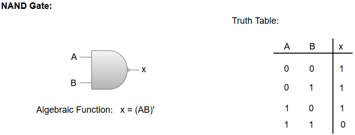
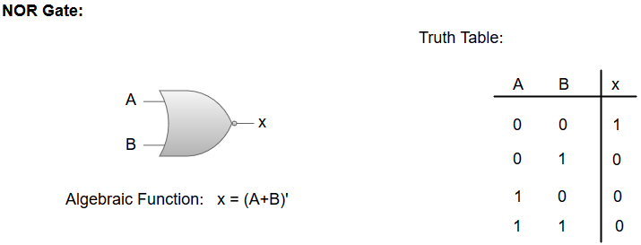
5. NOR Gate: NOR gate is the combination of or gate and NOT gate produces high (1) output when all inputs are low (o) Otherwise, the output will be low (0). It is the complement of the OR gate. It has two or more inputs and produces a single output.
Graphical symbols
6.Exclusive-OR\XOR: The ‘Exclusive-OR’ gate is a circuit that will give a high output if one of its inputs is high but not both of them. The XOR operation is represented by an encircled plus sign.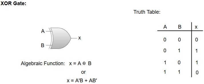
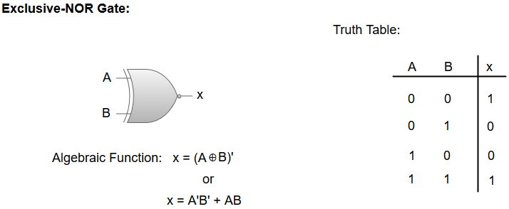
7. Exclusive-NOR’/Equivalence Gate
The ‘Exclusive-NOR’ gate is a circuit that does the inverse operation to the XOR gate. It will give a low output if one of its inputs is high but not both of them. The small circle represents inversion.

Thank you for your support